


Installations of submersible centrifugal pumps UETsN in a complete set
- from a submersible centrifugal pump (including check and drain valves, pump sections, inlet module);
- sludge trap (when ordering, it is negotiated separately);
- gas separator (when ordering, it is negotiated separately; when the unit is equipped with a gas separator with a receiving grid, the input module is not supplied);
- slotted filter – input module (when ordering, it is negotiated separately);
- hydroprotection;
- submersible motor;
- cable line;
- нground electrical equipment (control station, transformer, etc.);
- telemetry systems;
- tools, accessories, installation kits;
- spare parts (when ordering, it is negotiated separately);
Installations are developed at the most modern level. The design of the units is based on world-class technology, and materials designed specifically for submersible equipment and used in defense and space technology are used in its manufacture. The units allow pumping formation fluid with a capacity of 15 to 1250 m3/day. from a depth of up to 3600 m. The units are supplied in any configuration, which allows the consumer to have equipment suitable for any well.
Reservoir fluid – a mixture of oil, associated water and associated gas – has the following characteristics:
- maximum content of produced water, % — 99
- pH value of associated water, pH – 5.0…8.5;
- maximum liquid density, kg/m3 — 1400;
- maximum kinematic viscosity of a single-phase liquid, at which the operation of the pump is ensured without changing the pressure and efficiency mm2 / s – 1;
- maximum mass concentration of solid particles for pumps, g/l (%) –
standard version – 0.1 (0,01);
wear-resistant, corrosion-resistant design – 0.5 (0.05);
increased corrosion and wear resistance – 1.0 (0.10);
when pumps are equipped with a fine filter – 3.0 (0.30); - microhardness of particles according to Mohs for pumps, points – usual;
- increased corrosion and wear resistance, wear-resistant, corrosion-resistant design – 7
- the maximum content of free gas at the pump intake is 25% by volume, with the use of a gas separator as part of the installation – 55%, with the use of a gas separator-dispersant – 75%, with the use of an inlet dispersing module as part of the installation – 30%;
- maximum concentration of hydrogen sulfide for pumps, g/l (%) –
standard, iso-resistant design – 0.01 (0.001);
corrosion-resistant design;
increased corrosion and wear resistance – 1.25 (0.125); - maximum temperature of the pumped liquid, С — 150;
- maximum hydrostatic pressure in the installation suspension area, MPa -40;
- content of aggressive components, not more than – CO2 – 0.15 g/l, HCO3 – -1 g/l, Cl – -20g/l, Ca2+ – 2g/l (when using pumps of increased corrosion and wear resistance, corrosion and wear resistance, version).
Submersible Centrifugal Pumps (ESP)
Submersible centrifugal pumps are used to lift reservoir fluid, as well as in reservoir pressure maintenance systems. Taoilprom manufactures and supplies centrifugal submersible pumps in size groups 5, 5A and 6 with a capacity of 15 to 1250 m3/day. and pressure up to 3600 m. A wide range of pumps allows you to choose equipment for almost any operating conditions.
The pumps are designed according to the sectional principle and consist of an upper section (with a fishing head for attaching the pump to the tubing), middle sections, an inlet module, a gas separator, a check valve and a bleed valve.
Check valves have high tightness, which allows the consumer to pressure test tubing. Check valves can be manufactured with a pressure element of poppet or steam type (specified separately when ordering).
A submersible wire filter inlet to submersible pumps can also be used to receive reservoir fluid and separate solid impurities from it with a particle cross section of more than 0.1 or 0.2 mm.
With a high gas content in the reservoir fluid, a gas separator can be included in the pump.
Pump sections can be of various lengths, which ensures optimal selection of the pump for any well. Intermediate radial bearings are installed along the entire length of each section (see Fig.). Reliable long-term operation of pumps in various operating conditions is ensured by the optimal distance between the radial bearings.
Materials of impellers and guide vanes:
- modified gray cast iron (conventional pumps);
- modified cast iron with increased wear resistance (wear-resistant pumps);
- cast iron of the “niresist” type – pumps of corrosion-resistant design (corrosion-resistant design);
- hard cast iron of the “ni-resist” type with a hardness of up to 240 HB (pumps of increased corrosion and wear resistance);
- polymeric materials with special fillers. Impellers – polymer, guide devices – combined (with a polymer flow part or completely metal);
- high-strength and high-precision pump shafts can be made of stainless steel or K-monel and Alloy. Different execution of pumps allows delivering pumps characterized by increased thermal, corrosion and wear resistance.
Two-bearing pumps
ПThe use of an ESP with working stages of a two-support design allows the pump to be operated under difficult operating conditions associated with a high content of mechanical impurities. This design of the stages makes it possible to achieve a significant increase in the time between failures of the ESP. At the same time, the greater durability of the double-support pump is due to a significant decrease in the load per unit area of friction of the impeller washers.
The steps are extended in both directions, which allows:
- reduce vibration (increases the stability of the impeller due to the multiple increase in the length of the fit of the wheel on the shaft);
- close the shaft, providing its protection from hydroabrasive influence of formation fluid;
- virtually eliminate the cut of the key and turning the stage to the shaft (the length of the keyway of the impeller is multiplied, which minimizes the load on the key).
Special materials are used, designed to work in conditions of hydroabrasive wear – the working steps are made of ni-resist or modified (non-corrosion-resistant) cast iron with increased wear resistance.
The scope of delivery may include a set of tools and accessories necessary for the installation of a pumping unit on a well. All necessary spare parts can be supplied in any quantity.
Corrosion resistant pumps
New stages are used in the pump designs, which make it possible to increase the service life of the unit and reduce the cost per unit volume of oil produced at a nominal flow with maximum efficiency and minimum energy consumption.
| КОНСТРУКТИВНЫЕ ОСОБЕННОСТИ | СЕРИЯ 80 | СЕРИЯ 40 | СЕРИЯ 82 |
|---|---|---|---|
| В секции насоса отсутствует осевая опора вала | • | • | |
| Верхние подшипники вынесены из корпуса секции и встроены в головку | • | • | • |
| Нижние подшипники вынесены из корпуса секции и встроены в основание | • | • | • |
| Эвольвентное исполнение шлицевого соединения вала | • | • | • |
| Муфта вынесена из основания в головку секции | • | • | • |
| Защитные ребра перенесены с основания на головку | • | • | • |
| Радиальные подшипники унифицированной конструкции, оптимально расположенные по всей длине секции | • | • | • |
| Вал насоса находится в растянутом и выпрямленном состоянии | • | ||
| Колеса рабочие жестко зафиксированы на валу | • | ||
| Оригинальная схема регулировки заглубления вала с помощью специального приспособления (УМР), исключающего применение мерительного инструмента и сокращающего время монтажа | • | ||
| Рабочие ступени изготовлены из литого чугуна типа: “Серый чугун” “Нирезист” “Твердый нирезист” |
(ЭЦН) (ЭЦНКИ) |
• | • |
| Максимальная массовая концентрация твердых частииц, г/л | 0,2(ЭЦН) или 0,5(ЭЦНКИ) |
0,5 | 1,0 |
The new range of pumps offers an optimal arrangement of radial bearings along the entire length of the section, depending on the operating conditions. Radial bearings in pumps with a capacity of 250 m3/day and above are built into the working stage, which increases the pressure head of the pump section. The steps have a two-bearing design (up to 700 m3/day) or a single-bearing structure with an extended wheel hub (from 700 m3/day and more), the material of the working steps is selected depending on the operating conditions and customer requirements. Shafts in sections are involute and are made of high-strength stainless steel. Protective ribs are located in the head, which allows you to protect the cable in the upper part of the section and makes it easier to guide the cable when installing the unit. Pumps of series 80 can be manufactured in the usual version with gray cast iron working parts.
Distinctive features of pumps with a floating stage assembly scheme with an axial shaft support in sections, series 40 are:
- The pump sections have an axial shaft bearing made of silicon carbide ceramics.
- The impellers on the shaft have the possibility of axial movement by the allowable clearance, which simplifies the assembly of the pump and does not require the manufacture of stages of increased accuracy.
- It does not require any shaft offset adjustments.
- It is recommended to apply in conditions with the content of mechanical impurities up to 0.5 g/l.
Distinctive features of pumps with a floating stage assembly without axial shaft support in sections, series 80 are:
- The absence of axial shaft support in sections, which increases the service life of the pump and the installation as a whole due to the fact that the thrust bearing, which is located in the hydraulic protection and perceives the axial load, is protected from the impact of formation fluid abrasive.
- The impellers on the shaft have the possibility of axial movement by the allowable clearance, which simplifies the assembly of the pump and does not require increased accuracy to the stages during repairs.
- During the production assembly of sections, the shaft penetration into the head is set equal to the shaft overhang from the base side with the help of an adjusting bolt and washers.
- It is recommended to use in conditions with the content of mechanical impurities:
standard version up to 0.2 g/l;
corrosion-resistant version up to 0.5 g/l;
Distinctive features of pumps with a compression scheme for assembling stages of design 82 are:
- The hydrodynamic axial bearing of the shaft is installed in a hydraulic protection, has a low coefficient of friction and is not subject to abrasive wear.
- The impellers are tightened with a nut in one package and fixed on the shaft against axial movement.
- When installing the pump, the time-consuming operation of shimming is eliminated. The contact of the shafts of the pump sections is achieved by an adjusting bolt, which is fixed by a coupling against loosening. The procedure for adjusting the bolt during installation is simplified and is carried out by a special device without the use of measuring tools.
- It is recommended to apply in conditions with the content of mechanical impurities up to 1 g/l.
Specifications for ESP pumps
Pumps, depending on the transverse dimension, are manufactured in the following groups: 5, 5A, 6. The group conditionally determines the minimum inner diameter of the production string, the diameter of the pump casing and the motor.
| ГРУППА | 5 | 5А | 6 | ||
|---|---|---|---|---|---|
| Минимальный внутренний диаметр эксплуатационной колонны, мм | 121,3 | 124,3 | 130,7 | 144 | 148,3 |
| Диаметр корпуса насоса, мм | 92 | 103 | 114 | ||
| Диаметр корпуса электродвигателя | 103 | 117 | 117 | 130 односекц-й многосек-й | |
| Максимальный диаметральный габарит установки | 113,7 | 120,4 | 125,7 | 138,3 | |
The following structure of the symbol for the pump has been established when ordering, in correspondence and in other configurations.
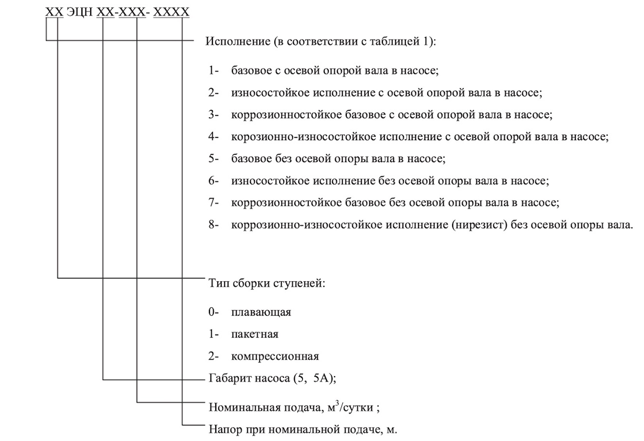
| ИСПОЛНЕНИЕ НАСОСОВ | ПРОИЗВОДИТЕЛЬНОСТЬ НАСОСОВ В РАБОЧЕЙ ЗОНЕ, М3/СУТ. | НАПОР НАСОСОВ, MIN…MAX, M | ПОТРЕБЛЯЕМАЯ МОЩНОСТЬ НАСОСОВ, MIN…MAX, КВТ |
|---|---|---|---|
| ЭЦН(КИ)5-15И | 10…22,5 | 180…3900 | 1,1…24,7 |
| ЭЦНКИ5-20И | 12…25 | 150…3750 | 1,3…28,1 |
| ЭЦНКИ5-25И | 18…32 | 150…3600 | 1,3…29,3 |
| ЭЦН(КИ)5-30И | 18…36 | 550…3550 | 5,4…34,8 |
| ЭЦНКИ5-35И | 25…45 | 500…3600 | 5,7…42,2 |
| ЭЦН5-45И | 35…55 | 500…3650 | 6,56…45,41 |
| ЭЦН(КИ)5-60И | 40…74 | 150…3600 | 2,0…47,0 |
| ЭЦН(КИ)5-80И | 60…100 | 150…3550 | 2,6…56,7 |
| ЭЦНКИ5-100И | 80…125 | 150…3550 | 3,0…72,8 |
| ЭЦН(КИ)5-125И | 60…165 | 150…3650 | 3,5…98,1 |
| ЭЦНКИ5-160 | 120…200 | 400…3500 | 14,56…127,95 |
| ЭЦН(КИ)5-200 | 130…230 | 300…3500 | 3,1…140,3 |
| ЭЦНКИ5А-50 | 25…80 | 600…3550 | 8,5…51,0 |
| ЭЦНКИ5А-60 | 40…80 | 200…3550 | 2,5…49,8 |
| ЭЦНКИ5А-80И | 60…100 | 200…3600 | 3,5…66,4 |
| ЭЦНКИ5А-100И | 70…130 | 200…3650 | 4,2…78,4 |
| ЭЦНКИ5А-125И | 75…175 | 200…3650 | 5,2…131,3 |
| ЭЦН(КИ)5А-160 | 125…195 | 150…3650 | 4,7…112,8 |
| ЭЦН(КИ)5А-200 | 125…250 | 150…3600 | 5,2…131,3 |
| ЭЦН(КИ)5А-250 | 180…300 | 150…3600 | 7,7…187,6 |
| ЭЦН(КИ)5А-400 | 300…440 | 250…2800 | 18,5…208,7 |
| ЭЦН(КИ)5А-500 | 375…650 | 200…2550 | 22,8…260,6 |
| ЭЦН(КИ)5А-700 | 540…960 | 150…2550 | 21,79…315,5 |
| ЭЦН(КИ)5А-800 | 640…960 | 150…2400 | 23,2…353,3 |
| ЭЦНКИ6-800 | 600…1000 | 200…3050 | 32,83…445,55 |
| ЭЦНКИ6-1250 | 950…1550 | 150…1900 | 35,52…447,55 |
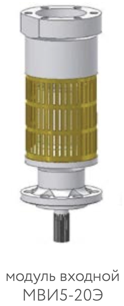
Input modules
The input module serves to receive reservoir fluid, to connect the pump to the motor and to transmit torque from the motor shaft to the shafts of the pump sections.
The input module consists of a base with holes for reservoir fluid intake and has plain bearings in which the shaft rotates. Outside, the base has a receiving grid (it may not be available at the request of the customer). To connect the shaft of the input module with the shaft of the hydraulic protection, a splined coupling is installed. With the help of resource studs or screws, the upper end of the input module is attached to the middle section of the pump or to the gas separator. The lower flange of the input module is attached to the engine hydraulic protection using studs and nuts.
TECHNICAL SPECIFICATIONS OF INPUT MODULES
| НАИМЕНОВАНИЕ МОДУЛЕЙ ВХОДНОГО | ДИАМЕТР ВАЛА, ММ | МОНТАЖНАЯ ДЛИНА, ММ | ДИАМЕТР КОРПУСА, ММ | МАССА, КГ |
|---|---|---|---|---|
| МВИ5-20Э | 20 | 302 | 103 | 12,8 |
| МВИ5А-25Э | 25 | 302 | 108 | 14,1 |
| МВИ6-28Э | 28 | 302 | 123 | 15 |
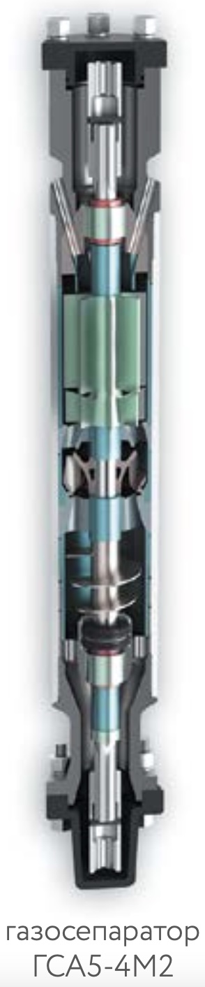
Gas separators, dispersants
Gas separators, dispersants and gas separators-dispersers are designed to ensure stable operation of submersible centrifugal pumps when pumping formation fluid with a high content of free gas.
The gas separator is indispensable for oil production from wells with a high content of dissolved gas. It is installed at the pump inlet instead of the inlet module or after the inlet module when the gas separator is designed without a receiving grid. Taoilprom manufactures and supplies efficient gas separators for various operating conditions for all types of pumps.
The principle of operation of the gas separator is based on the use of centrifugal force to remove free gas. The gas is removed into the nozzle space, while eliminating the formation of gas plugs in the pump, which ensures stable operation of the ESP and increases the time between failures.
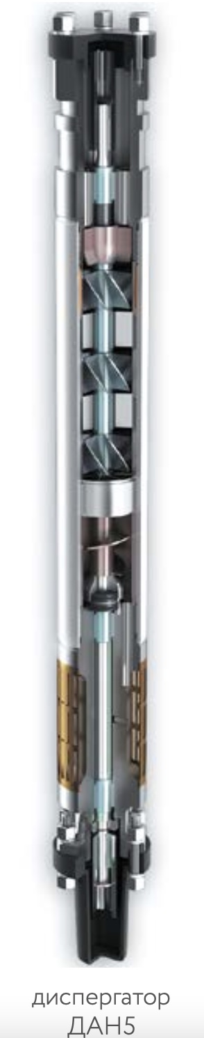
The dispersant is intended for grinding gas inclusions in the reservoir fluid, preparing a homogeneous gas-liquid mixture and feeding it to the inlet of a submersible centrifugal pump. When the flow of the gas-liquid mixture passes through the disperser, its homogeneity and the degree of fineness of gas inclusions increase, which improves the operation of the centrifugal pump, reduces its vibration and pulsation of flows in the tubing, and ensures operation with a given efficiency.
Gas separators-dispersants are installed at the pump inlet instead of a gas separator or a dispersant in wells with a particularly high GOR, where the use of neither a gas separator nor a dispersant ensures stable operation of a submersible centrifugal pump.
Application conditions
Gas separators, dispersants, gas separators-dispersants (hereinafter referred to as products) are designed for use in reservoir fluid with the following parameters.
- Maximum content of free gas at the inlet, :
gas separators 55
dispersants 30..40
gas separators-dispersers 75 - Temperature of pumped liquid, С 150
- Hydrogen index, pH 5.0…8.5
- Concentration of solid particles in reservoir fluid, g/l 1.0
- Microhardness of particles on the Mohs scale, points, no more than 7
- Maximum concentration of hydrogen sulfide, g/l 1.25
- Maximum content of produced water, % 99
- Maximum liquid density, kg/m3 1400
- Maximum kinematic viscosity of a single-phase fluid, which ensures the operation of the product without changing the pressure and efficiency, mm2/s 1
Design features
In the design of products, the friction pairs of radial bearings are made of hard alloy. The axial bearing is made of ceramic. The end pieces and protective sleeves of the housings are made of corrosion resistant steel to increase resistance to hydroabrasive wear. The parts of the flow part of the products are made of corrosion-resistant steel and cast iron of the “ni-resist” type of increased corrosion and wear resistance with a hardness of up to 190..240 HB. It is possible to execute the base with receiving holes of a shortened type without a grid.
All products are produced in corrosion-resistant design.
TECHNICAL DATA
The rotation frequency (synchronous) of the product shaft is 3000 rpm. When the product is made without axial shaft support, its shaft rests on the protector shaft. In the case of using a product with a base without a receiving grid, an input module should be used as part of the pump. Other parameters of gas separators, gas separator-dispersants and dispersants are shown in the tables below.
Gas separator
| НАИМЕНОВАНИЕ ГАЗОСЕПАРАТОРА | КОЭФФИЦИЕНТ СЕПАРЦИИ ГАЗА, НЕ МЕНН | ПОДАЧА В РАБОЧЕЙ ЗОНЕ, М3/СУТ. | ПОДАЧА(НОМИНАЛЬНОЕ ЗНАЧЕНИЕ), М3/СУТ | МОЩНОСТЬ ПОТРЕБЛЯЕМАЯ MAX, КВТ | ТИП СОЕДИНЕНИЯ: ГОЛОВКА(“КОРПУС”), ММ | ТИП СОЕДИНЕНИЯ: ОСНОВАНИЕ(“ФЛАНЕЦ”), ММ | ДИАМЕТР ВАЛА, ММ | ЗАГЛУБЛЕНИЕ ВАЛА, ММ | ВЫЛЕТ ВАЛА (РАБОЧЕЕ ПОЛОЖЕНИЕ), ММ | ДЛИНА МОНТАЖНАЯ, ММ | ДИАМЕТР КОРПУСА, ММ | МАССА, КГ |
|---|---|---|---|---|---|---|---|---|---|---|---|---|
| 2ГС5(Э) | 0,50 | 15…280 | 250 | 1,5 | 8 отв. М10х1 межцентр. ⌀83 | 8 отв. ⌀11 межцентр. ⌀83 | 20 | 45+-5,3 | 25 +3,5 -2,5 | 830 | 92 | 33 |
| ГСН5(Э) | 0,50 | 15…280 | 250 | 1,5 | 6 отв. М12х1,25 межцентр. ⌀83 | 6 отв. ⌀13 межцентр. ⌀83 | 20 | 45+-5,3 | 42 +3,1 -5,8 | 940 | 92 | 35 |
| 2ГСН5(Э) | 0,50 | 15…280 | 250 | 1,5 | 8 отв. М10х1 межцентр. ⌀83 | 6 отв. ⌀13 межцентр. ⌀83 | 20 | 45+-5,3 | 42 +3,1 -5,8 | 940 | 92 | 35 |
| ГСО5-4M2(Э) | 0,50 | 15…280 | 250 | 1,5 | 6 отв. М12х1,25 межцентр. ⌀83 | 6 отв. ⌀13 межцентр. ⌀83 | 20 | 25+-0,5 | 23 +-0,1 | 830 | 92 | 34,5 |
| ГСОН5(Э) | 0,50 | 15…280 | 250 | 1,5 | 6 отв. М12х1,25 межцентр. ⌀83 | 6 отв. ⌀13 межцентр. ⌀83 | 20 | 25+-0,5 | 58+-0,1 | 830 | 92 | 36 |
| ГСО5-250 | 0,50 | 15…280 | 250 | 1,5 | 6 отв. М12х1,25 межцентр. ⌀83 | 6 отв. ⌀13 межцентр. ⌀83 | 20 | 44+-0,5 | 22 +-0,1 | 830 | 92 | 34,5 |
| 1ГСО5-250 | 0,50 | 15…280 | 250 | 1,5 | 8 отв. М12х1,25 межцентр. ⌀81 | 8 отв. ⌀11 межцентр. ⌀81 | 20 | 44+-0,5 | 42 +-0,1 | 830 | 92 | 34,5 |
| 2ГСО5-250 | 0,50 | 15…280 | 250 | 1,5 | 8 отв. М10х1 межцентр. ⌀83 | 8 отв. ⌀11 межцентр. ⌀83 | 20 | 44+-0,5 | 42 +-0,1 | 830 | 92 | 34,5 |
| ГСОН5-250 | 0,50 | 15…280 | 250 | 1,5 | 8 отв. М10х1 межцентр. ⌀83 | 6 отв. ⌀13 межцентр. ⌀83 | 20 | 44+-0,5 | 58 +-0,1 | 940 | 92 | 36 |
| 2ГСО5-250 | 0,50 | 15…280 | 250 | 1,5 | 8 отв. М10х1 межцентр. ⌀83 | 6 отв. ⌀13 межцентр. ⌀83 | 20 | 44+-0,5 | 58 +-0,1 | 940 | 92 | 36 |
| ГС5А(Э) | 0,5 | 25…600 | 500 | 2,2 | 6 отв. М12х1,25 межцентр. ⌀88 | 6 отв. ⌀13 межцентр. ⌀88 | 22 | 45+-5,3 | 25+3,5-2,5 | 965 | 103 | 34,5 |
| ГСН5А(Э) | 0,50 | 25…680 | 500 | 2,2 | 6 отв. М12х1,25 межцентр. ⌀88 | 6 отв. ⌀13 межцентр. ⌀83 | 22 | 45+-5,3 | 42+3,1-5,6 | 1094 | 103 | 38,8 |
| 2ГСН5А(Э) | 0,50 | 25…600 | 500 | 2,2 | 8 отв. М10х1 межцентр. ⌀88 | 6 отв. ⌀13 межцентр. ⌀83 | 22 | 45+-5,3 | 42+3,1-5,8 | 1094 | 103 | 40,1 |
| 3ГСН5А(Э) | 0,50 | 25…600 | 500 | 2,2 | 6 отв. М12х1,25 межцентр. ⌀83 | 6 отв. ⌀13 межцентр. ⌀83 | 22 | 45+-5,3 | 42+3,1-5,8 | 1094 | 103 | 38,4 |
| 4ГСН5А(Э) | 0,50 | 25…600 | 500 | 2,2 | 6 отв. М12х1,25 межцентр. ⌀83 | 6 отв. ⌀13 межцентр. ⌀83 | 22 | 45+-5,3 | 42+3,1-5,8 | 1094 | 103 | 38,4 |
| ГСО5А(Э) | 0,50 | 25…600 | 500 | 2,2 | 6 отв. М12х1,25 межцентр. ⌀88 | 6 отв. ⌀13 межцентр. ⌀88 | 22 | 29+2 | 23+-0,1 | 965 | 103 | 35,5 |
| ГСОН5А(Э) | 0,50 | 25…600 | 500 | 2,2 | 6 отв. М12х1,25 межцентр. ⌀88 | 6 отв. ⌀13 межцентр. ⌀83 | 22 | 29+2 | 58+-0,1 | 1094 | 103 | 39,4 |
| 2ГСОН5А(Э) | 0,50 | 25…600 | 500 | 2,2 | 8 отв. М10х1 межцентр. ⌀88 | 6 отв. ⌀13 межцентр. ⌀83 | 22 | 29+2 | 58+-0,1 | 1094 | 103 | 41,5 |
| 3ГСОН5А(Э) | 0,50 | 25…600 | 500 | 2,2 | 6 отв. М12х1,25 межцентр. ⌀88 | 6 отв. ⌀13 межцентр. ⌀83 | 22 | 29+2 | 58+-0,1 | 1094 | 103 | 39,4 |
| 4ГСОН5А(Э) | 0,50 | 25…600 | 500 | 2,2 | 6 отв. М12х1,25 межцентр. ⌀88 | 6 отв. ⌀13 межцентр. ⌀88 | 22 | 44+0,5 | 42+-0,1 | 1094 | 103 | 39,4 |
| ГСО5А-500 | 0,50 | 25…600 | 500 | 2,2 | 6 отв. М12х1,25 межцентр. ⌀88 | 6 отв. ⌀13 межцентр. ⌀88 | 22 | 44+0,5 | 42+-0,1 | 1005 | 103 | 35 |
| 2ГСО5А-500 | 0,50 | 25…600 | 500 | 2,2 | 8 отв. М10х1 межцентр. ⌀88 | 6 отв. ⌀13 межцентр. ⌀88 | 22 | 44+0,5 | 42+-0,1 | 1005 | 103 | 38 |
| ГСОН5А-500 | 0,50 | 25…600 | 500 | 2,2 | 6 отв. М12х1,25 межцентр. ⌀88 | 6 отв. ⌀13 межцентр. ⌀83 | 22 | 44+0,5 | 58+-0,1 | 1134 | 103 | 40 |
| 2ГСОН5А-500 | 0,50 | 25…600 | 500 | 2,2 | 8 отв. М10х1 межцентр. ⌀88 | 6 отв. ⌀13 межцентр. ⌀83 | 22 | 44+0,5 | 58+-0,1 | 1134 | 103 | 41 |
| 3ГСОН5А-500 | 0,50 | 25…600 | 500 | 2,2 | 6 отв. М12х1,25 межцентр. ⌀83 | 6 отв. ⌀13 межцентр. ⌀83 | 22 | 44+0,5 | 58+-0,1 | 1134 | 103 | 39 |
| 4ГСОН5А-500 | 0,50 | 25…600 | 500 | 2,2 | 6 отв. М12х1,25 межцентр. ⌀83 | 6 отв. ⌀13 межцентр. ⌀83 | 22 | 44+0,5 | 58+-0,1 | 1134 | 103 | 40 |
Gas separators-dispersants
| НАИМЕНОВАНИЕ ГАЗОСЕПАРАТОРА | КОЭФФИЦИЕНТ СЕПАРЦИИ ГАЗА, НЕ МЕНН | ПОДАЧА В РАБОЧЕЙ ЗОНЕ, М3/СУТ. | ПОДАЧА(НОМИНАЛЬНОЕ ЗНАЧЕНИЕ), М3/СУТ | МОЩНОСТЬ ПОТРЕБЛЯЕМАЯ MAX, КВТ | ТИП СОЕДИНЕНИЯ: ГОЛОВКА(“КОРПУС”), ММ | ТИП СОЕДИНЕНИЯ: ОСНОВАНИЕ(“ФЛАНЕЦ”), ММ | ДИАМЕТР ВАЛА, ММ | ЗАГЛУБЛЕНИЕ ВАЛА, ММ | ВЫЛЕТ ВАЛА (РАБОЧЕЕ ПОЛОЖЕНИЕ), ММ | ДЛИНА МОНТАЖНАЯ, ММ | ДИАМЕТР КОРПУСА, ММ | МАССА, КГ |
|---|---|---|---|---|---|---|---|---|---|---|---|---|
| ГСДО5-250 | 0,50 | 15…280 | 250 | 2,2 | 6 отв. М12х1,25 межцентр. ⌀83 | 6 отв. ⌀13 межцентр. ⌀83 | 20 | 44+-0,5 | 42+-0,1 | 1499 | 92 | 59 |
| 1ГСДО5-250 | 0,50 | 15…280 | 250 | 2,2 | 8 отв. М12х1,25 межцентр. ⌀81 | 8 отв. ⌀13 межцентр. ⌀81 | 20 | 44+-0,5 | 42+-0,1 | 1499 | 92 | 59 |
| 2ГСДО5-250 | 0,50 | 15…280 | 250 | 2,2 | 8 отв. М10х1 межцентр. ⌀83 | 8 отв. ⌀11 межцентр. ⌀83 | 20 | 44+-0,5 | 42+-0,1 | 1609 | 92 | 59 |
| ГСДОН5-250 | 0,50 | 15…280 | 250 | 2,2 | 6 отв. М12х1,25 межцентр. ⌀83 | 6 отв. ⌀13 межцентр. ⌀83 | 20 | 44+-0,5 | 58+-0,1 | 1609 | 92 | 60 |
| 2ГСДОН5-250 | 0,50 | 15…280 | 250 | 2,2 | 8 отв. М10х1 межцентр. ⌀83 | 6 отв. ⌀13 межцентр. ⌀83 | 20 | 44+-0,5 | 58+-0,1 | 1609 | 92 | 60 |
| ГСДОН5-250 | 0,50 | 15…280 | 250 | 2,2 | 6 отв. М12х1,25 межцентр. ⌀83 | 6 отв. ⌀13 межцентр. ⌀83 | 20 | 44+-0,5 | 58+-0,1 | 1322 | 92 | 43 |
| ГСДО5-250 | 0,50 | 15…280 | 250 | 2,2 | 6 отв. М12х1,25 межцентр. ⌀83 | 6 отв. ⌀13 межцентр. ⌀83 | 20 | 44+-0,5 | 42+-0,1 | 1253 | 92 | 42 |
| 2ГСДОН5-250 | 0,50 | 15…280 | 250 | 2,2 | 8 отв. М10х1 межцентр. ⌀83 | 6 отв. ⌀13 межцентр. ⌀83 | 20 | 44+-0,5 | 58+-0,1 | 1322 | 92 | 43 |
| 2ГСДО5-250 | 0,50 | 15…280 | 250 | 2,2 | 8 отв. М10х1 межцентр. ⌀83 | 8 отв. ⌀13 межцентр. ⌀83 | 20 | 44+-0,5 | 42+-0,1 | 1253 | 92 | 42 |
| 1ГСДО5-250 | 0,50 | 15…280 | 250 | 2,2 | 8 отв. М12х1,25 межцентр. ⌀81 | 8 отв. ⌀13 межцентр. ⌀81 | 20 | 44+-0,5 | 42+-0,1 | 1253 | 92 | 41 |
| ГСД5А | 0,50 | 25…950 | 500 | 2,5 | 6 отв. М12х1,25 межцентр. ⌀88 | 6 отв. ⌀13 межцентр. ⌀88 | 22 | 45+-5,3 | 25+3,5-2,5 | 1380 | 103 | 44,1 |
| ГСДН5А | 0,50 | 25…950 | 500 | 2,5 | 6 отв. М12х1,25 межцентр. ⌀88 | 6 отв. ⌀13 межцентр. ⌀83 | 22 | 45+-5,3 | 25+3,1-5,8 | 1478 | 103 | 45 |
| ГСДО5А-25Э | 0,50 | 25…950 | 500 | 2,5 | 6 отв. М12х1,25 межцентр. ⌀88 | 6 отв. ⌀13 межцентр. ⌀83 | 25 | 61+1,6-2,95 | 58+0,1 | 1500 | 103 | 48 |
| ГСДО5А-25 | 0,50 | 25…950 | 500 | 2,5 | 6 отв. М12х1,25 межцентр. ⌀88 | 6 отв. ⌀13 межцентр. ⌀83 | 25 | 29+-0,5 | 58+-0,2 | 1500 | 103 | 48 |
| ГСДОН5А-500 | 0,50 | 25…950 | 500 | 2,5 | 6 отв. М12х1,25 межцентр. ⌀88 | 6 отв. ⌀13 межцентр. ⌀83 | 25 | 44+-0,5 | 58+-0,1 | 1478 | 103 | 45 |
| ГСДО5А-500 | 0,50 | 25…950 | 500 | 2,5 | 6 отв. М12х1,25 межцентр. ⌀88 | 6 отв. ⌀13 межцентр. ⌀88 | 25 | 44+-0,5 | 42+-0,1 | 1349 | 103 | 40 |
| ГСДОН6-1000 | 0,6 | 600…1550 | 1000 | 5 | 6 отв. М12х1,25 межцентр. ⌀100 | 6 отв. ⌀13 межцентр. ⌀88 | 28 | 44+-0,5 | 58+-0,1 | 1720 | 114 | 72 |
| 2ГСДОН6-1000 | 0,6 | 600…1550 | 1000 | 5 | 8 отв. М10х1 межцентр. ⌀83 | 6 отв. ⌀13 межцентр. ⌀83 | 28 | 44+-0,5 | 58+-0,1 | 1720 | 114 | 72 |
| ГСДО6-1000 | 0,6 | 600…1550 | 1000 | 5 | 6 отв. М12х1,25 межцентр. ⌀100 | 6 отв. ⌀13 межцентр. ⌀83 | 28 | 44+-0,5 | 42+-0,1 | 1612 | 114 | 70 |
| 2ГСДО6-1000 | 0,6 | 600…1550 | 1000 | 5 | 8 отв. М10х1 межцентр. ⌀83 | 6 отв. ⌀11 межцентр. ⌀83 | 28 | 44+-0,5 | 42+-0,1 | 1612 | 114 | 70 |
Dispersants
| НАИМЕНОВАНИЕ ГАЗОСЕПАРАТОРА | ПОДАЧА В РАБОЧЕЙ ЗОНЕ, М3/СУТ. | ПОДАЧА(НОМИНАЛЬНОЕ ЗНАЧЕНИЕ), М3/СУТ | МОЩНОСТЬ ПОТРЕБЛЯЕМАЯ MAX, КВТ | ТИП СОЕДИНЕНИЯ: ГОЛОВКА(“КОРПУС”), ММ | ТИП СОЕДИНЕНИЯ: ОСНОВАНИЕ(“ФЛАНЕЦ”), ММ | ДИАМЕТР ВАЛА, ММ | ЗАГЛУБЛЕНИЕ ВАЛА, ММ | ВЫЛЕТ ВАЛА (РАБОЧЕЕ ПОЛОЖЕНИЕ), ММ | ДЛИНА МОНТАЖНАЯ, ММ | ДИАМЕТР КОРПУСА, ММ | МАССА, КГ |
|---|---|---|---|---|---|---|---|---|---|---|---|
| ДО5-250 | 12…280 | 250 | 1 | 6 отв. М12х1,25 межцентр. ⌀83 | 6 отв. ⌀13 межцентр. ⌀83 | 20 | 44+-0,5 | 42+-0,1 | 669 | 92 | 24 |
| 1ДО5-250 | 12…280 | 250 | 1 | 8 отв. М12х1,25 межцентр. ⌀81 | 8 отв. ⌀13 межцентр. ⌀81 | 20 | 44+-0,5 | 42+-0,1 | 669 | 92 | 24 |
| 2ДО5-250 | 12…280 | 250 | 1 | 8 отв. М10х1 межцентр. ⌀83 | 8 отв. ⌀11 межцентр. ⌀83 | 20 | 44+-0,5 | 42+-0,1 | 669 | 92 | 24 |
| ДОН5-250 | 12…280 | 250 | 1 | 6 отв. М12х1,25 межцентр. ⌀83 | 6 отв. ⌀13 межцентр. ⌀83 | 20 | 44+-0,5 | 58+-0,1 | 779 | 92 | 26 |
| 2ДОН5-250 | 12…280 | 250 | 1 | 8 отв. М10х1 межцентр. ⌀83 | 6 отв. ⌀13 межцентр. ⌀83 | 20 | 44+-0,5 | 58+-0,1 | 779 | 92 | 26 |
| ДН5А | 25…600 | 500 | 1,5 | 6 отв. М12х1,25 межцентр. ⌀83 | 6 отв. ⌀13 межцентр. ⌀83 | 22 | 45+-5,3 | 42+5,3-5,6 | 805 | 103 | 23 |
| ДОН5А-500 | 25…600 | 500 | 1,5 | 6 отв. М12х1,25 межцентр. ⌀83 | 6 отв. ⌀13 межцентр. ⌀83 | 22 | 45+-5,3 | 42+5,3-5,8 | 805 | 103 | 29,5 |
| ДО5А-500 | 25…600 | 500 | 1,5 | 6 отв. М12х1,25 межцентр. ⌀83 | 6 отв. ⌀13 межцентр. ⌀83 | 22 | 44+-0,5 | 42+-0,1 | 664 | 103 | 20 |
Hydroprotection
Main parametres of water protection
| ТИП ГИДРОЗАЩИТЫ | МОЩНОСТЬ ПОТРЕБЛЯЕМАЯ (БЕЗ ОСНОВНОЙ НАГРУЗКИ), КВТ | МОЩНОСТЬ ПОТРЕБЛЯЕМАЯ (ПРИ МАХ НАГРУЗКЕ), КВТ | МОЩНОСТЬ ПЕРЕДАВАЕМАЯ, КВТ | ДИАМЕТР ПО КОРПУСУ, ММ | ДЛИНА ПРИСОЕДИНИТЕЛЬНАЯ, ММ | МАССА, КГ | ОБЪЕМ МАСЛА, Л | МАКСИМАЛЬНО ДОПУСТИМАЯ ОСЕВАЯ НАГРУЗКА НА ПЯТУ, КГ |
|---|---|---|---|---|---|---|---|---|
| Г(К)Т(1)М5ЛД(Э) | 0,35 | 1,40 | 125 | 92 | 2155 | 65 | 3,7 | 750 |
| Г(К)Т(1)М5ЛДД(Э) | 0,45 | 1,40 | 125 | 92 | 3095 | 90 | 6,0 | 750 |
| Г(К)Т(1)М5Л2Д(Э) | 0,45 | 1,40 | 180 | 92 | 3095 | 90 | 6,0 | 750 |
| Г(К)Т(1)М5ЛДЭ ОУ | 0,45 | 1,80 | 125 | 92 | 2155 | 65 | 3,7 | 3500 |
| Г(К)Т(1)М5ЛДД(Э) ОУ | 0,45 | 1,80 | 125 | 92 | 3095 | 90 | 6,0 | 3500 |
| Г(К)Т(1)М5Л2Д(Э) ОУ | 0,45 | 1,80 | 180 | 92 | 3095 | 90 | 6,0 | 3500 |
| Г(К)Т(1)М5АЛД(Э) | 0,60 | 1,60 | 160 | 103 | 2195 | 84 | 4,9 | 800 |
| Г(К)Т(1)М5АЛДД(Э) | 0,60 | 1,60 | 160 | 103 | 3136 | 110 | 8,0 | 800 |
| Г(К)Т(1)М5АЛ2Д(Э) | 0,60 | 1,60 | 360 | 103 | 3136 | 110 | 8,0 | 800 |
| Г(К)Т(1)М5АЛДД(Э) ОУ | 0,60 | 2,00 | 160 | 103 | 3136 | 110 | 7,5 | 3500 |
| Г(К)Т(1)М5АЛ2Д(Э) ОУ | 0,60 | 2,00 | 160 | 103 | 3136 | 110 | 7,5 | 3500 |
| Г(К)Т(1)М6ЛД(Э) | 0,80 | 1,80 | 360 | 114 | 2581 | 120 | 5,6 | 900 |
| Г(К)Т(1)М6ЛДД(Э) | 0,80 | 1,80 | 360 | 114 | 3551 | 160 | 9,0 | 900 |
| Г(К)Т(1)М6Л2Д(Э) | 0,80 | 1,80 | 550 | 114 | 3551 | 160 | 9,0 | 900 |
| Г(К)Т(1)М6Л2ДД(Э) ОУ | 0,80 | 2,40 | 360 | 114 | 3551 | 160 | 9,0 | 8160 |
| Г(К)Т(1)М6Л2ДЭ ОУ | 0,80 | 2,40 | 550 | 114 | 3551 | 160 | 9,0 | 8160 |
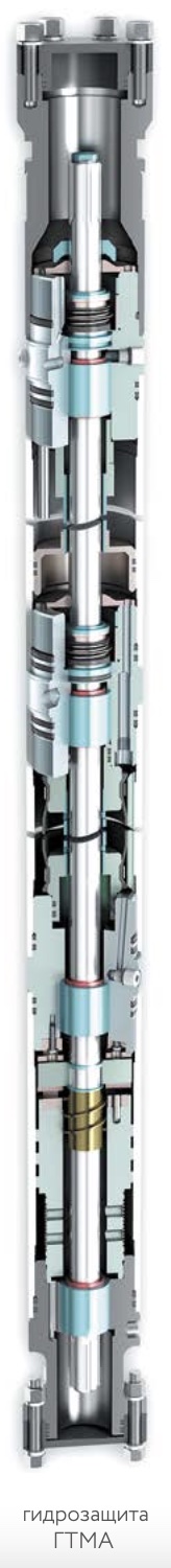
Design of hydraulic protection:
- all types of hydraulic protection are made in a monoblock modular design;
- compatibility of hydraulic protection with submersible motors (with the right rotation of the shaft) of other manufacturers;
- hydroprotection of the 5th size can be made with a combined input module with a receiving grid;
- hydroprotectors of 5 and 5A dimensions can be made of a tandem type, consisting of two protectors;
- hydroprotection of any type can be made in a corrosion-resistant design (K);
- hydroprotection of any type can be made in a high-temperature-resistant design (T1). Such hydraulic protections are operable at formation fluid temperatures up to 150 °C (at the special request of the consumer, hydraulic protections are manufactured with mechanical rubber goods operable up to 250 °С;
- tandem-type hydraulic protection can be made in a super-heat-resistant design (T2) and be operable at formation fluid temperatures up to 180 °C;
- application of mechanical seals of leading domestic and foreign companies in hydraulic protections (at the special request of the consumer, hydraulic protections are equipped with mechanical seals that are operable at a temperature of 250 ° C;
- equipping with bypass check valves, which provide bleeding of excess internal pressure and removal of the free gas phase from the oil cavity of the SEM during the operation of the ESP;
- the use of an elastic bandage of the diaphragm in hydraulic protection, which ensures the removal of gas and excess oil from the internal cavity of the engine to the annulus, makes it possible to abandon gas valves;
- execution of hydroprotection shafts from high-strength stainless steel;
- the presence in the design of the filter-cooler, designed to filter and cool the oil in the area of the heel assembly;
- the presence of a reinforced heel assembly for the perception of axial load from the pump.
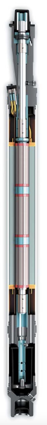
Electric motors (EM)
Oil-filled three-phase asynchronous two (four) pole electric motors with a squirrel-cage rotor (hereinafter referred to as EM) are used as a drive for centrifugal pumps for pumping formation fluid from oil wells with an angle of deviation from the vertical at the suspension point of no more than 250 °. An electric motor complete with hydraulic protection is called an engine (hereinafter – SEM).
Electric motors of the following overall groups are produced:
| ГАБАРИТ, ММ | МОЩНОСТЬ, КВТ |
|---|---|
| 103 | 16…180 |
| 117 | 12…350 |
| 130 | 22…550 |
LLC “Taoilprom” produces electric motors of various capacities, which allows you to choose the most optimal combination of “engine-pump” to ensure the operation of the installation with the highest possible efficiency.
The manufacturing technology determines the high quality and reliability of submersible electric motors manufactured by Taoilprom LLC. The use of special electrical materials makes it possible to operate motors at formation fluid temperatures up to 120 °C in a highly heat-resistant design – up to 150 °C.
After assembly on special stands, which control the quality of individual components, the electric motor is tested at a test station under conditions close to real, including heating to operating temperatures. 100% of electric motors are tested, after testing they are all disassembled and carefully checked. Verification of the polarization index is carried out during the tests.
According to the requirements of consumers, electric motors can be equipped with: shafts and couplings with an involute profile; centralizers screwed into the base of the electric motor and preventing contact of the electric motor body with the casing string; jacks for smooth mounting of sectional electric motors.
Versions of electric motors by the availability of telemetry
| НОМЕР МОДИФИКАЦИИ | ОТЛИЧИТЕЛЬНЫЕ ОСОБЕННОСТИ ИСПОЛНЕНИЯ ЭЛЕКТРОДВИГАТЕЛЕЙ |
|---|---|
| 3 | Электродвигатель с телеметрией ТРИОЛ ТМ-01 производства ООО «Триол-нефть» г. Москва. ТМСП встраивается под основание ЭД |
| 4 | лектродвигатель с системой контроля скважинной СКАД-2002В-СКС производства ООО «Нефтяные измерительные системы» г. Москва. Преобразователь скважинный многоканальный (ПСМ), встраивается в основание ЭД |
| 5 | Электродвигатель с системой телеметрии производства ООО «НПО ЭТАЛОН», встраивается под основанием ЭД |
| 6 | Электродвигатель с телеметрией ИРЗ ТМС производства ДООО «ИРЗ ТЭК», г. Ижевск. Блок погружной БП-103 встраивается под основанием ЭД |
| 7 | Электродвигатель с телеметрией Ижнефтемаш, БПТ устанавливается под основание ЭД |
| 8 | Электродвигатель с телеметрией ЭЛЕКТОН-ТМС-3 производства ЗАО «ЭЛЕКТОН» г. Радужный. ТМСП встраивается под основание ЭД |
| 9 | Электродвигатель с телеметрией ЭЛЕКТОН-ТМС-3 производства ЗАО «ЭЛЕКТОН» г. Радужный. ТМСП встраивается в основание ЭД |
| 42,62 или 92 | Электродвигатель без установленного погружного блока (под ТМС) телеметрии СКАД-2002СКС или ЭЛЕКТОН-ТМСП-3 соответственно, предназначенный для установки погружного блока у потребителя |
Electric motors EDT16…80-103M1
| ТИП ЭЛЕКТРОДВИГАТЕЛЯ | НОМИНАЛЬНАЯ МОЩНОСТЬ, КВТ | НОМИНАЛЬНОЕ НАПРЯЖЕНИЕ, В | НОМИНАЛЬНЫЙ ТОК, А | КПД, % | COS, Ф | СКОЛЬЖЕНИЕ, % | МИН. ДИАМЕТР СКВАЖИН, ММ | СКОРОСТЬ ОХЛАЖДАЮЩЕЙ ЖИДКОСТИ, НЕ МЕНЕЕ М/С | КОЛИЧЕСТВО ПАЕТОВ РОТОРА, ШТ | КОЛИЧЕСТВО СЕКЦИЙ, ШТ | ДЛИНА, ММ | МАССА, КГ | МОМЕНТ ПРОВОРАЧИВАНИЯ ВАЛА, КГС-М |
|---|---|---|---|---|---|---|---|---|---|---|---|---|---|
| ЭДТ16-103М1 | 16 | 530 | 25,6 | 81,0 | 0,84 | 5,8 | 121,7 | 0,07 | 6 | 1 | 3005 | 160 | 0,15 |
| ЭДТ22-103М1 | 22 | 700 | 27,5 | 81,0 | 0,83 | 5,5 | 121,7 | 0,10 | 8 | 1 | 3685 | 200 | 0,25 |
| ЭДТ28-103М1 | 28 | 900 | 27,0 | 81,0 | 0,82 | 5,8 | 121,7 | 0,10 | 10 | 1 | 4365 | 240 | 0,30 |
| ЭДТ32-103М1 | 32 | 1000 | 27,5 | 81,0 | 0,83 | 5,9 | 121,7 | 0,10 | 11 | 1 | 4705 | 260 | 0,35 |
| ЭДТ40-103М1 | 40 | 1200 | 30,0 | 81,5 | 0,84 | 5,8 | 121,7 | 0,15 | 13 | 1 | 5385 | 300 | 0,40 |
| ЭДТ45-103М1 | 45 | 1400 | 28,0 | 81,5 | 0,83 | 5,4 | 121,7 | 0,15 | 15 | 1 | 6065 | 339 | 0,45 |
| ЭДТ50-103М1 | 50 | 1400 | 32,0 | 81,0 | 0,83 | 6,0 | 121,7 | 0,20 | 15 | 1 | 6065 | 339 | 0,45 |
| ЭДТ56-103М1 | 56 | 1600 | 32,0 | 81,0 | 0,83 | 6,0 | 121,7 | 0,30 | 16 | 1 | 6405 | 358 | 0,50 |
| ЭДТ63-103М1 | 63 | 1750 | 32,0 | 81,0 | 0,83 | 6,0 | 121,7 | 0,35 | 17 | 1 | 6745 | 377 | 0,55 |
| ЭДТ70-103М1 | 70 | 1900 | 30,2 | 82,0 | 0,83 | 6,5 | 121,7 | 0,35 | 18 | 1 | 7085 | 398 | 0,55 |
| ЭДТ80-103М1 | 80 | 2050 | 36,0 | 80,0 | 0,83 | 7,2 | 121,7 | 0,30 | 21 | 1 | 8140 | 405 | 0,75 |
Synchronous shaft speed – 3000 rpm.
Electric motors EDST90…180-103M3
| ТИП ЭЛЕКТРОДВИГАТЕЛЯ | НОМИНАЛЬНАЯ МОЩНОСТЬ, КВТ | НОМИНАЛЬНОЕ НАПРЯЖЕНИЕ, В | НОМИНАЛЬНЫЙ ТОК, А | КПД, % | COS, Ф | СКОЛЬЖЕНИЕ, % | МИН. ДИАМЕТР СКВАЖИН, ММ | СКОРОСТЬ ОХЛАЖДАЮЩЕЙ ЖИДКОСТИ, НЕ МЕНЕЕ М/С | КОЛИЧЕСТВО ПАЕТОВ РОТОРА, ШТ | КОЛИЧЕСТВО СЕКЦИЙ, ШТ | ДЛИНА, ММ | МАССА, КГ | МОМЕНТ ПРОВОРАЧИВАНИЯ ВАЛА, КГС-М |
|---|---|---|---|---|---|---|---|---|---|---|---|---|---|
| ЭДТ90-103М3 | 90 | 2000 | 40 | 82,0 | 0,84 | 5,6 | 121,7 | 0,20 | 28 | 2 | 11184 | 660 | 0,70 |
| ЭДТ100-103М3 | 100 | 2120 | 42 | 81,0 | 0,84 | 6,0 | 121,7 | 0,25 | 30 | 2 | 11184 | 680 | 0,75 |
| ЭДТ110-103М3 | 110 | 2060 | 49 | 81,5 | 0,83 | 6,4 | 121,7 | 0,30 | 34 | 2 | 13222 | 700 | 1,00 |
| ЭДТ125-103М3 | 125 | 2560 | 44 | 81,0 | 0,84 | 7,0 | 121,7 | 0,35 | 36 | 2 | 13904 | 730 | 0,90 |
| ЭДТ140-103М3 | 140 | 2500 | 51 | 81,0 | 0,83 | 6,5 | 121,7 | 0,30 | 40 | 2 | 15262 | 795 | 1,00 |
| ЭДТ150-103М3 | 150 | 3820 | 36 | 80,0 | 0,83 | 7,0 | 121,7 | 0,20 | 40 | 2 | 15262 | 795 | 1,00 |
| ЭДТ180-103М3 | 180 | 3150 | 52 | 80,5 | 0,83 | 6,5 | 121,7 | 0,20 | 51 | 3 | 19572 | 1060 | 1,2 |
Synchronous shaft speed – 3000 rpm.
Electric motors EDT12…125M(M6)
| ТИП ЭЛЕКТРОДВИГАТЕЛЯ | НОМИНАЛЬНАЯ МОЩНОСТЬ, КВТ | НОМИНАЛЬНОЕ НАПРЯЖЕНИЕ, В | НОМИНАЛЬНЫЙ ТОК, А | КПД, % | COS, Ф | СКОЛЬЖЕНИЕ, % | МИН. ДИАМЕТР СКВАЖИН, ММ | СКОРОСТЬ ОХЛАЖДАЮЩЕЙ ЖИДКОСТИ, НЕ МЕНЕЕ М/С | КОЛИЧЕСТВО ПАЕТОВ РОТОРА, ШТ | КОЛИЧЕСТВО СЕКЦИЙ, ШТ | ДЛИНА, ММ | МАССА, КГ | МОМЕНТ ПРОВОРАЧИВАНИЯ ВАЛА, КГС-М |
|---|---|---|---|---|---|---|---|---|---|---|---|---|---|
| ЭДТ12-117М | 12 | 380 | 26,0 | 84,0 | 0,85 | 5,0 | 123,7 | 0,05 | 3 | 1 | 2110 | 132 | 0,20 |
| ЭДТ16-117М | 16 | 750 | 18,0 | 84,0 | 0,85 | 5,0 | 123,7 | 0,05 | 4 | 1 | 2490 | 62 | 0,20 |
| ЭДТ20-117М | 20 | 630 | 27,0 | 84,5 | 0,86 | 5,2 | 123,7 | 0,05 | 5 | 1 | 2870 | 190 | 0,35 |
| ЭДТ22-117М | 22 | 750 | 24,0 | 84,5 | 0,85 | 5,0 | 123,7 | 0,05 | 6 | 1 | 3250 | 228 | 0,35 |
| ЭДТ24-117М | 24 | 800 | 25,0 | 84,5 | 0,86 | 5,2 | 123,7 | 0,08 | 6 | 1 | 3250 | 218 | 0,35 |
| ЭДТ28-117М | 28 | 900 | 26,0 | 84,5 | 0,84 | 5,0 | 123,7 | 0,08 | 7 | 1 | 3620 | 246 | 0,40 |
| ЭДТ32-117М | 32 | 1000 | 26,0 | 85,0 | 0,84 | 5,0 | 123,7 | 0,08 | 8 | 1 | 4020 | 274 | 0,45 |
| ЭДТ36-117М | 36 | 1200 | 25,0 | 84,5 | 0,86 | 5,0 | 123,7 | 0,08 | 9 | 1 | 4390 | 302 | 0,50 |
| ЭДТ40-117М | 36 | 1280 | 26,0 | 84,5 | 0,86 | 5,2 | 123,7 | 0,08 | 9 | 1 | 4770 | 330 | 0,55 |
| ЭДТ45-117М | 45 | 1400 | 26,0 | 85,0 | 0,86 | 5,0 | 123,7 | 0,08 | 11 | 1 | 5150 | 358 | 0,60 |
| ЭДТ50-117М | 50 | 1400 | 28,0 | 84,5 | 0,86 | 5,2 | 123,7 | 0,12 | 12 | 1 | 5530 | 389 | 0,60 |
| ЭДТ56-117М | 56 | 1400 | 32,0 | 84,5 | 0,86 | 5,2 | 123,7 | 0,12 | 13 | 1 | 5910 | 418 | 0,70 |
| ЭДТ63-117М | 63 | 2000 | 25,0 | 85,0 | 0,85 | 5,2 | 123,7 | 0,30 | 15 | 1 | 5667 | 471 | 0,80 |
| ЭДТ70-117М | 70 | 1900 | 31,0 | 84,5 | 0,84 | 5,2 | 123,7 | 0,20 | 16 | 1 | 7050 | 498 | 0,80 |
| ЭДТ80-117М | 80 | 2000 | 35,0 | 84,0 | 0,84 | 6,0 | 123,7 | 0,30 | 16 | 1 | 7090 | 508 | 0,60 |
| ЭДТ90-117М | 90 | 1900 | 39,0 | 84,5 | 0,84 | 5,2 | 123,7 | 0,30 | 18 | 1 | 7810 | 554 | 0,90 |
| ЭДТ90-117М | 90 | 2300 | 34,0 | 84,0 | 0,84 | 6,0 | 123,7 | 0,30 | 16 | 1 | 7470 | 538 | 0,60 |
| ЭДТ100-117М | 100 | 2100 | 40,0 | 84,5 | 0,86 | 5,2 | 123,7 | 0,30 | 19 | 1 | 8190 | 582 | 1,0 |
| ЭДТ100-117М | 100 | 2500 | 34,0 | 84,0 | 0,84 | 6,0 | 123,7 | 0,30 | 17 | 1 | 7850 | 552 | 0,80 |
| ЭДТ110-117М | 110 | 2300 | 40,0 | 84,0 | 0,84 | 6,0 | 123,7 | 0,30 | 18 | 1 | 8230 | 571 | 0,90 |
| ЭДТ125-117М | 125 | 2400 | 44,0 | 83,5 | 0,85 | 6,2 | 123,7 | 0,30 | 19 | 1 | 8230 | 571 | 0,90 |
Synchronous shaft speed – 3000 rpm.
Electric motors EDTS80…350-117M(4,6)
| ТИП ЭЛЕКТРОДВИГАТЕЛЯ | НОМИНАЛЬНАЯ МОЩНОСТЬ, КВТ | НОМИНАЛЬНОЕ НАПРЯЖЕНИЕ, В | НОМИНАЛЬНЫЙ ТОК, А | КПД, % | COS, Ф | СКОЛЬЖЕНИЕ, % | МИН. ДИАМЕТР СКВАЖИН, ММ | СКОРОСТЬ ОХЛАЖДАЮЩЕЙ ЖИДКОСТИ, НЕ МЕНЕЕ М/С | КОЛИЧЕСТВО ПАЕТОВ РОТОРА, ШТ | КОЛИЧЕСТВО СЕКЦИЙ, ШТ | ДЛИНА, ММ | МАССА, КГ | МОМЕНТ ПРОВОРАЧИВАНИЯ ВАЛА, КГС-М |
|---|---|---|---|---|---|---|---|---|---|---|---|---|---|
| ЭДТC80-117М | 80 | 2000 | 34,0 | 84,5 | 0,830 | 5,2 | 130 | 0,30 | 18 | 2 | 8471 | 573 | 1,0 |
| ЭДТC90-117М | 90 | 2000 | 41,0 | 85,0 | 0,830 | 5,2 | 130 | 0,30 | 20 | 2 | 9231 | 629 | 1,2 |
| ЭДТC100-117М | 100 | 2000 | 41,0 | 85,0 | 0,850 | 5,2 | 130 | 0,30 | 22 | 2 | 9991 | 687 | 1,3 |
| ЭДТC110-117М | 110 | 2300 | 40,0 | 84,5 | 0,860 | 5,2 | 130 | 0,30 | 22 | 2 | 9750 | 687 | 1,4 |
| ЭДТC125-117М | 125 | 2400 | 45,0 | 84,5 | 0,830 | 5,2 | 130 | 0,30 | 30 | 2 | 10510 | 743 | 1,4 |
| ЭДТC140-117М | 140 | 2600 | 45,5 | 84,5 | 0,860 | 5,2 | 130 | 0,50 | 32 | 2 | 12030 | 855 | 1,4 |
| ЭДТC160-117М | 160 | 2300 | 61,0 | 84,5 | 0,840 | 5,2 | 130 | 0,50 | 28 | 2 | 13550 | 967 | 1,4 |
| ЭДТC180-117М | 180 | 2400 | 63,0 | 84,0 | 0,850 | 5,2 | 130 | 0,50 | 36 | 2 | 15311 | 1095 | 1,8 |
| ЭДТC200-117М | 200 | 2500 | 66,5 | 84,5 | 0,860 | 5,2 | 130 | 0,50 | 36 | 2 | 15830 | 1135 | 1,8 |
| ЭДТC220-117М | 220 | 2700 | 68,0 | 84,5 | 0,860 | 5,2 | 130 | 0,50 | 38 | 2 | 16590 | 1191 | 1,8 |
| ЭДТC250-117М | 250 | 3200 | 68,0 | 82,0 | 0,830 | 6,5 | 130 | 0,80 | 38 | 2 | 16145 | 1135 | 1,8 |
| ЭДТC300-117М | 300 | 2880 | 90,0 | 83,0 | 0,830 | 5,8 | 130 | 1,10 | 45 | 3 | 19397 | 1373 | 2,4 |
| ЭДТC350-117М | 350 | 3750 | 79,0 | 82,5 | 0,850 | 6,0 | 130 | 1,10 | 54 | 3 | 22772 | 1608 | 2,4 |
Synchronous shaft speed – 3000 rpm.
Electric motors EDT22…32-117/4M
| ТИП ЭЛЕКТРОДВИГАТЕЛЯ | НОМИНАЛЬНАЯ МОЩНОСТЬ, КВТ | НОМИНАЛЬНОЕ НАПРЯЖЕНИЕ, В | НОМИНАЛЬНЫЙ ТОК, А | КПД, % | COS, Ф | СКОЛЬЖЕНИЕ, % | МИН. ДИАМЕТР СКВАЖИН, ММ | СКОРОСТЬ ОХЛАЖДАЮЩЕЙ ЖИДКОСТИ, НЕ МЕНЕЕ М/С | КОЛИЧЕСТВО ПАЕТОВ РОТОРА, ШТ | КОЛИЧЕСТВО СЕКЦИЙ, ШТ | ДЛИНА, ММ | МАССА, КГ | МОМЕНТ ПРОВОРАЧИВАНИЯ ВАЛА, КГС-М |
|---|---|---|---|---|---|---|---|---|---|---|---|---|---|
| ЭДТ22-117/4М | 22 | 650 | 38 | 68 | 0,78 | 11,0 | 123,7 | 0,08 | 10 | 1 | 4757,5 | 330 | 0,5 |
| ЭДТ28-117/4М | 28 | 900 | 38 | 70 | 0,70 | 10,5 | 123,7 | 0,08 | 14 | 1 | 6277,5 | 445 | 0,6 |
| ЭДТ32-117/4М | 32 | 950 | 40 | 70 | 0,65 | 10,0 | 123,7 | 0,10 | 14 | 1 | 6277,5 | 445 | 0,5 |
Asynchronous shaft speed – 1500 rpm.
Electric motors EDT22…180-130M
| ТИП ЭЛЕКТРОДВИГАТЕЛЯ | НОМИНАЛЬНАЯ МОЩНОСТЬ, КВТ | НОМИНАЛЬНОЕ НАПРЯЖЕНИЕ, В | НОМИНАЛЬНЫЙ ТОК, А | КПД, % | COS, Ф | СКОЛЬЖЕНИЕ, % | МИН. ДИАМЕТР СКВАЖИН, ММ | СКОРОСТЬ ОХЛАЖДАЮЩЕЙ ЖИДКОСТИ, НЕ МЕНЕЕ М/С | КОЛИЧЕСТВО ПАЕТОВ РОТОРА, ШТ | КОЛИЧЕСТВО СЕКЦИЙ, ШТ | ДЛИНА, ММ | МАССА, КГ | МОМЕНТ ПРОВОРАЧИВАНИЯ ВАЛА, КГС-М |
|---|---|---|---|---|---|---|---|---|---|---|---|---|---|
| ЭДТ22-130М | 22 | 800 | 23 | 85 | 0,84 | 5,5 | 144 | 0,6 | 2 | 1 | 2000 | 162 | 0,25 |
| ЭДТ32-130М | 32 | 1200 | 22 | 85 | 0,85 | 5,5 | 144 | 0,6 | 3 | 1 | 2495 | 191 | 0,40 |
| ЭДТ40-130М | 40 | 1300 | 26 | 85 | 0,85 | 5,5 | 144 | 0,6 | 3 | 1 | 2495 | 191 | 0,45 |
| ЭДТ75-130М | 75 | 1500 | 40 | 85 | 0,85 | 5,5 | 144 | 0,5 | 6 | 1 | 3980 | 378 | 0,60 |
| ЭДТ90-130М | 90 | 1600 | 46 | 85 | 0,84 | 5,0 | 144 | 0,6 | 7 | 1 | 4476 | 369 | 0,60 |
| ЭДТ125-130М | 125 | 1800 | 56 | 85 | 0,84 | 5,0 | 144 | 0,6 | 11 | 1 | 6455 | 621 | 0,80 |
| ЭДТ150-130М | 150 | 2700 | 45 | 85 | 0,85 | 5,8 | 144 | 0,6 | 13 | 1 | 7445 | 639 | 1,10 |
| ЭДТ150-130М | 150 | 2700 | 45 | 85 | 0,85 | 5,8 | 144 | 0,6 | 13 | 1 | 7445 | 639 | 1,10 |
| ЭДТ180-130М | 180 | 2400 | 63 | 84 | 0,84 | 6,0 | 144 | 0,6 | 14 | 1 | 7940 | 696 | 1,40 |
Shaft synchronous speed – 1500 rpm.
Electric motors EDTS180…550-130M
| ТИП ЭЛЕКТРОДВИГАТЕЛЯ | НОМИНАЛЬНАЯ МОЩНОСТЬ, КВТ | НОМИНАЛЬНОЕ НАПРЯЖЕНИЕ, В | НОМИНАЛЬНЫЙ ТОК, А | КПД, % | COS, Ф | СКОЛЬЖЕНИЕ, % | МИН. ДИАМЕТР СКВАЖИН, ММ | СКОРОСТЬ ОХЛАЖДАЮЩЕЙ ЖИДКОСТИ, НЕ МЕНЕЕ М/С | КОЛИЧЕСТВО ПАЕТОВ РОТОРА, ШТ | КОЛИЧЕСТВО СЕКЦИЙ, ШТ | ДЛИНА, ММ | МАССА, КГ | МОМЕНТ ПРОВОРАЧИВАНИЯ ВАЛА, КГС-М |
|---|---|---|---|---|---|---|---|---|---|---|---|---|---|
| ЭДСТ180-130М | 180 | 2300 | 62 | 84 | 0,85 | 6,0 | 148,3 | 0,7 | 16 | 2 | 9703 | 866 | 1,4 |
| ЭДСТ230-130М | 230 | 2400 | 78 | 85,0 | 0,85 | 5,80 | 148,3 | 1,1 | 18 | 2 | 10691 | 946 | 2,2 |
| ЭДСТ250-130М | 250 | 2700 | 76 | 85,0 | 0,85 | 5,80 | 148,3 | 1,1 | 20 | 2 | 11681 | 1026 | 2,6 |
| ЭДСТ300-130М | 300 | 3000 | 85,7 | 85,0 | 0,82 | 5,0 | 148,3 | 1,1 | 28 | 2 | 15646 | 1415 | 2,8 |
| ЭДСТ320-130М | 320 | 2800 | 95,0 | 84,0 | 0,84 | 5,80 | 148,3 | 1,0 | 26 | 2 | 14651 | 1310 | 2,6 |
| ЭДСТ360-130М | 360 | 3000 | 99 | 85,0 | 0,84 | 5,80 | 148,3 | 1,1 | 28 | 2 | 15641 | 1390 | 2,8 |
| ЭДСТ400-130М | 400 | 3000 | 105 | 83,0 | 0,84 | 5,80 | 148,3 | 2,8 | 30 | 2 | 16631 | 1470 | 2,8 |
| ЭДСТ460-130М | 460 | 3200 | 115 | 85,0 | 0,88 | 5,0 | 148,3 | 1,1 | 39 | 3 | 21958 | 1931 | 4,2 |
| ЭДСТ500-130М | 500 | 3600 | 120 | 85,0 | 0,87 | 5,0 | 148,3 | 1,1 | 42 | 3 | 23430 | 2056 | 4,2 |
Shaft synchronous speed – 1500 rpm.
Covers for submersible motors for sizes 103, 117
| ТИП КОЖУХА | КОЛИЧЕСТВО СЕКЦИЙ, ШТ. | ТИП КОЖУХА | КОЛИЧЕСТВО СЕКЦИЙ, ШТ. |
|---|---|---|---|
| КЭ103-5-124-05МВ | 1 | КЭ103-5-124-13МВ | 2 |
| КЭ103-5-124-06МВ | 1 | КЭ103-5-124-14МВ | 2 |
| КЭ103-5-124-07МВ | 1 | КЭ103-5-124-15МВ | 3 |
| КЭ103-5-124-08МВ | 2 | КЭ103-5-124-16МВ | 3 |
| КЭ103-5-124-09МВ | 2 | КЭ103-5-124-17МВ | 3 |
| КЭ103-5-124-10МВ | 2 | КЭ103-5-124-18МВ | 3 |
| КЭ103-5-124-11МВ | 2 | КЭ103-5-124-19МВ | 3 |
| КЭ103-5-124-12МВ | 2 | КЭ103-5-124-20МВ | 3 |
Casings KE117-(A)-140-04N…KE117-5(A)-140-42N are used for completing electric motors with a size of 117 mm
| ТИП КОЖУХА | КОЛИЧЕСТВО СЕКЦИЙ, ШТ. | ТИП КОЖУХА | КОЛИЧЕСТВО СЕКЦИЙ, ШТ. |
|---|---|---|---|
| КЭ117-5(А)-140-04Н | 1 | КЭ117-5(А)-140-24Н | 4 |
| КЭ117-5(А)-140-05Н | 1 | КЭ117-5(А)-140-25Н | 4 |
| КЭ117-5(А)-140-06Н | 1 | КЭ117-5(А)-140-26Н | 4 |
| КЭ117-5(А)-140-07Н | 1 | КЭ117-5(А)-140-27Н | 4 |
| КЭ117-5(А)-140-04Н | 2 | КЭ117-5(А)-140-28Н | 4 |
| КЭ117-5(А)-140-09Н | 2 | КЭ117-5(А)-140-29Н | 5 |
| КЭ117-5(А)-140-10Н | 2 | КЭ117-5(А)-140-30Н | 5 |
| КЭ117-5(А)-140-11Н | 2 | КЭ117-5(А)-140-31Н | 5 |
| КЭ117-5(А)-140-12Н | 2 | КЭ117-5(А)-140-32Н | 5 |
| КЭ117-5(А)-140-13Н | 2 | КЭ117-5(А)-140-33Н | 5 |
| КЭ117-5(А)-140-14Н | 2 | КЭ117-5(А)-140-34Н | 5 |
| КЭ117-5(А)-140-15Н | 2 | КЭ117-5(А)-140-35Н | 5 |
| КЭ117-5(А)-140-16Н | 3 | КЭ117-5(А)-140-36Н | 6 |
| КЭ117-5(А)-140-17Н | 3 | КЭ117-5(А)-140-37Н | 6 |
| КЭ117-5(А)-140-18Н | 3 | КЭ117-5(А)-140-38Н | 6 |
| КЭ117-5(А)-140-19Н | 3 | КЭ117-5(А)-140-39Н | 6 |
| КЭ117-5(А)-140-20Н | 3 | КЭ117-5(А)-140-40Н | 6 |
| КЭ117-5(А)-140-21Н | 3 | КЭ117-5(А)-140-41Н | 6 |
| КЭ117-5(А)-140-22Н | 4 | КЭ117-5(А)-140-42Н | 6 |
| КЭ117-5(А)-140-23Н | 4 |
- Casings for electric motors are used in those wells where, due to the large inner diameter of the casing string, the flow rate of the pumped liquid washing the electric motor does not provide sufficient cooling for it, they are designed to increase the flow rate of the pumped liquid in order to ensure cooling of electric motors in oil wells.
- Each motor diameter has its own casing size. The length of the casing depends on the length of the intended electric motor and hydraulic protection.
- Casings are made single-section and multisection. In the manufacture of multi-section casings, the connection between the sections is carried out using threaded couplings.
- Casings with a length of more than 7 meters are made sectional.
- Enclosures for 103 mm electric motors are hung on a special pump input module using threaded screws.
- Casings for electric motors with a size of 117 mm are hung to the base of the lower section of the pump using a clamp for suspension, respectively, for dimensions of 5.5 A.
- The casings are completed with a centralizer installed in the base of the electric motor during installation in order to ensure its uniform washing during operation.
- Housing mounting hardware is available upon separate order.
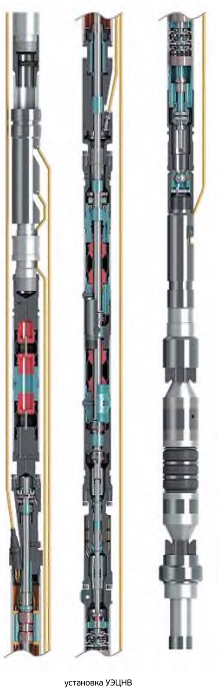
VERTICAL WATER INJECTION UNIT
Several types of centrifugal water injection units are produced.
The UETsNV reservoir water injection unit is an individual submersible unit that allows you to selectively inject water into selected wells.
UETsNV units for pumping water into reservoirs have a number of advantages over other types of similar equipment:
- long service life;
- ease of operation – the unit is located underground and does not require a special room for its installation;
- the ability to select the characteristics of pressure and productivity for a single well;
- high maintainability.
Structurally, the installation is made according to an inverted scheme relative to traditional ESPs. The fluid flow is directed from top to bottom, ensuring the injection of water into the formation. The injection zone is packaged, thereby separating from the liquid supply zone. The liquid is fed from the top of the column. In conditions of remote location of wells from the main communications and other reservoir pressure maintenance systems, the use of these units is optimal. Installations for pumping water from reservoir to reservoir can be equipped with a downhole flowmeter to measure the flow and pressure at the outlet of the pump.
It is completed with ETsNV pumps of the 5th, 5A dimensions.
INSTALLATION TOOLS AND SPARE PARTS
To perform works on the installation of installations at the well, LLC Taoilprom offers a full set of necessary tools and accessories.
Mounting tool:
- special keys,
- moment wrenches,
- reinforced wrenches,
- megaohmmeter.
Other necessary tool is located in a case, convenient for carrying.
Accessories include:
- filling pump,
- crimping cover,
- pedestal, clamp-elevator, suspension.
At the request of the consumer, tools and accessories can be supplied in any range and quantity for both existing and newly equipped fields.
For the repair of a submersible unit after the expiration of the warranty period of its operation, all necessary spare parts (installation elements) can be supplied in any range and in any quantity.